
The Problem
FPrimeC was retained by Gillespie Building Consultants Inc. (Client) to perform non-destructive evaluation and testing on three (3) upturn concrete beams located at the parking garage of a condominium building in Ajax, Ontario. Concrete elements under investigation were three (3) concrete beams at specified locations of the parking roof. At the time of inspection, extensive cracking was observed on the surfaces of concrete beams (inside and outside). The cracks were inclined and more frequent in number and severity near the supports (concrete walls). The main objective of the project was visual and non-destructive inspection of concrete beams at select areas; including map existing cracks, map location of transverse reinforcement, and measure width and depth of cracks.
Testing Methodology
A site visit and meeting with Client was performed to discuss the test areas and communicate project objectives. Following the preliminary site visit, a testing plan including (close-up) visual inspection of existing cracks, and non-destructive testing (NDT) on concrete beams was proposed.
Visual Inspection
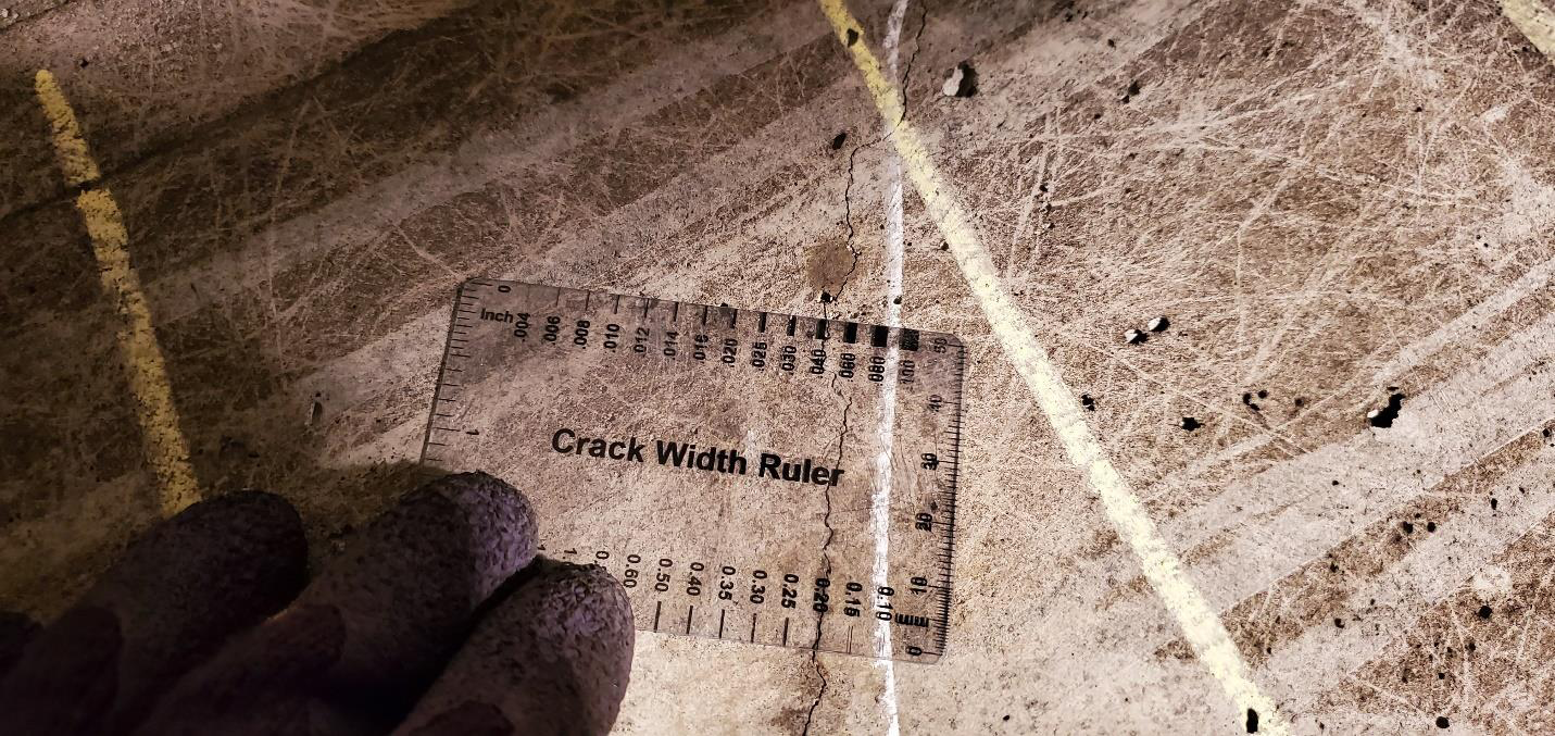 The visual inspection involved arm-length inspection of cracks, and other potential surface defects. All major visible cracks and surface defects such as concrete delamination were marked for preparation of engineering drawings. A crack width gauge was used to determine the width of cracks at two locations along each crack (one at the top, and one at the bottom end). The cracks width and severity were determined according to the Ontario Structure Inspection Manual (OSIM, 2008) guidelines.
Non-Destructive Testing
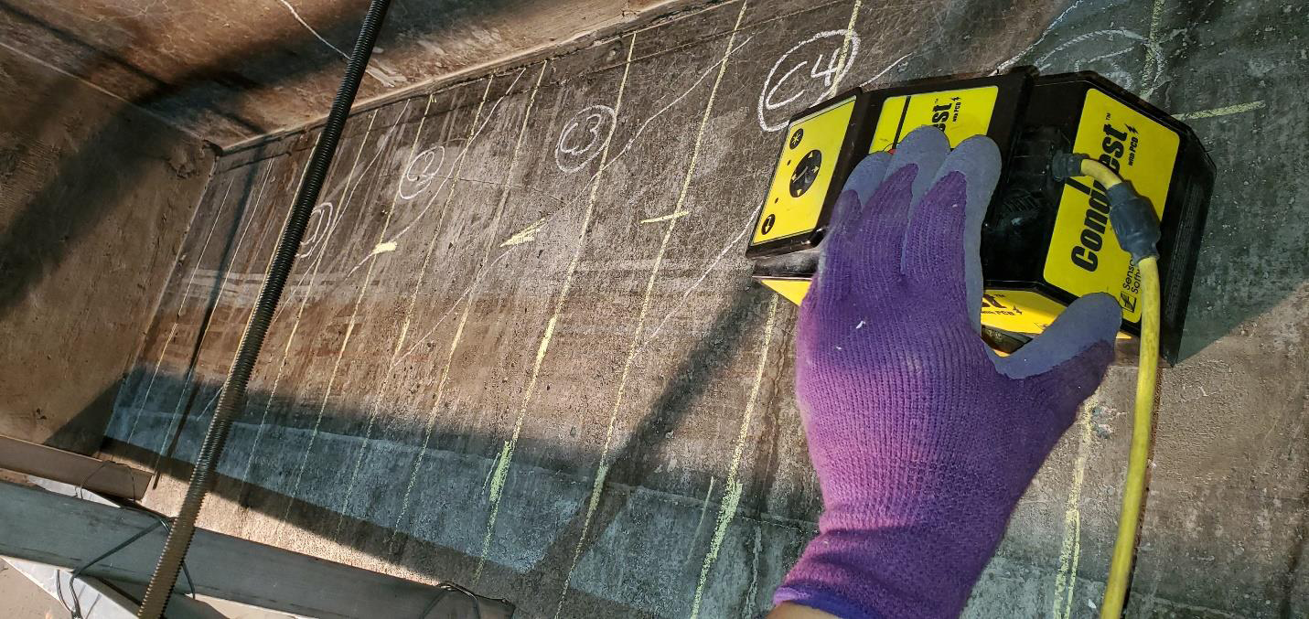 On each concrete beam, further inspection and testing was performed in the test areas using nondestructive testing (NDT). Two (2) NDT test methods including Ground Penetrating Radar (GPR) and Ultrasonic Pulse Velocity (UPV) were utilized in this project.
Ground Penetrating Radar (GPR) was used to verify the location and spacing of steel reinforcement. A line scan was used to verify the location of transverse reinforcement (i.e. stirrups) in the beams. At few locations, the test was performed to verify the location of longitudinal bars in the center of the beam.
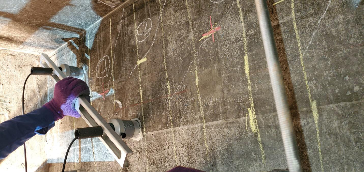
Ultrasonic Pulse Velocity (UPV) was used to estimate the depth of cracks over select cracks, wherever cracks were accessible. The selection criterion was based on the type, extent, severity of cracks (crack width) at each test area.