FPrimeC Solutions was hired by a contractor to perform proof load testing of concrete structure. The structural element under investigation was a Q-Deck slab with premature sign of cracking which warranted further assessment. The concrete slab comprised of Q-Deck with concrete topping. The access to the soffit was limited due to presence of insulations and other mechanical utilities. Due to the complex geometry (variable thickness), assessing the structural integrity using conventional Non-destructive Testing and evaluation (NDT-E) was not feasible. In the absence of a reliable testing solution, the contractor and engineer of records opted for proof load testing of the slab at two different spans.
Solution: Proof Load Testing of Concrete Structure
Proof load testing of concrete structure was proposed to assess the load-deformation response of the slab. The method allowed engineers to determine deflections at various locations of the slab during the loading and unloading process.
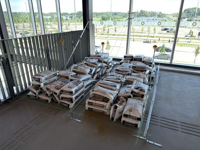
Loading Concrete Slab
Sand bags were used for the purpose of loading the slab. The target load was specified by the EOR. The number of sand bags were adjusted to achieve the target load at increments.
Deflection Measurement
Two different methods for deflection measurements were proposed and implemented.
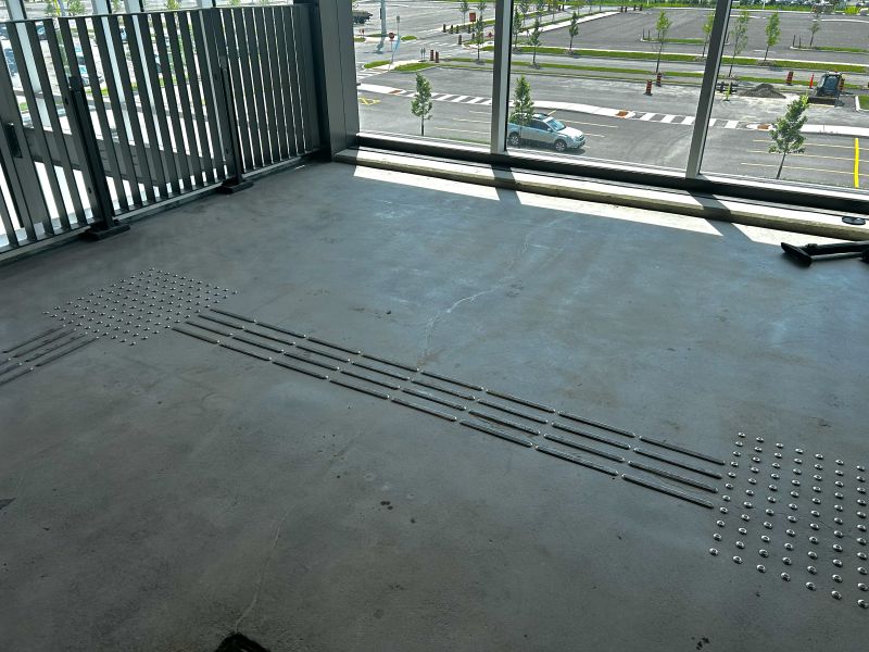
Method 1 – LVDT
involved installing LVDTs on the top of the slab to measure differential movements at any given time during the loading process. A separate test frame, isolated from the test area was designed and constructed to allow installation of displacement sensors at various locations across the slab (mid span, and perimeter beams).
Method 2 – Total Station and Prisms
Several prisms were installed at the location of interest. A total station was installed at a distance, and monitored the vertical displacement of prisms at each load sequence. Unlike LVDTs, the measurements for the displacement were discrete, and only collected when the loading was stopped.

Load-Deformation Response
At each loading and unloading increment, the loading paused, and deflections were measured using both methods. The two approach delivered generally consistent results, with minor deviations due to the precision of surveying equipment. The deflections at each location was compared against the maximum allowable displacement. The approach helped client verify the adequacy of the slab in a time and cost effective approach.