In this article, the basic principles and the advantages of Ground Penetrating Radar (GPR) in concrete scanning and its comparison to other concrete scanning NDT techniques will be presented. This technique is greatly beneficial to contractors and engineers working in the construction industry.
What is Ground Penetrating Radar?
Ground Penetrating Radar (GPR) technology has been available since the early 1970s. It is a cost-effective, non-destructive test used to scan and locate embedded objects from the surface. It is a useful tool in concrete scanning to identify subsurface defects such as voids and corrosion. GPR has three main components. Two of which are essential, namely, the console, which is the brain of the system that initiates a signal and records responses, and the antenna, where an electromagnetic wave signal is produced. The third one is the encoder with wheels for locational accuracy, which has a transmitter and a receiver controlled by the console.
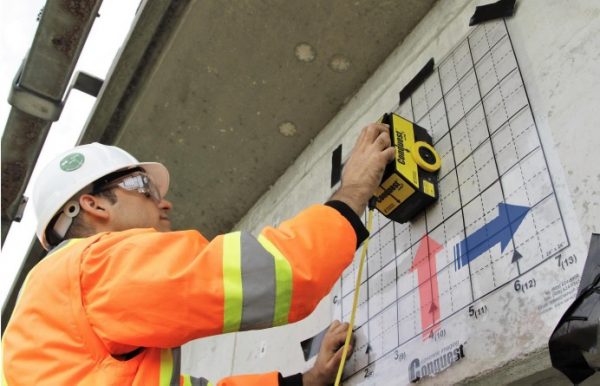
How GPR works in Concrete Scanning?
An electromagnetic wave is sent into the concrete surface. This wave will travel into the subsurface until it decays or bounced back due to the changed physical properties. Its reflected components are gathered and analyzed. This produces a one-dimensional view combined with other signals to create a profile or a 3D image. The image created depends on the amount of energy that bounces back (also known as reflection, R), which relies on the difference between the acoustic (wave velocity) and the two overlapping materials’ magnetic properties. It affects how a material underneath can be seen or blocked from an overlying material. This material property is called the dielectric constant or its electrical susceptibility. In general, materials with high wave velocity have low dielectric constants. The signal passing through them dissipates slower such as concrete. In contrast, materials with low wave velocity have high dielectric constants, and the signal passing through them dissipate faster. Air has a dielectric constant of 1, which is lower than concrete. On the other hand, steel has a very high dielectric constant. This is why concrete and air have partial signal reflection while concrete and steel have a total signal reflection, which creates high amplitudes.
Strengths and Weaknesses of GPR
1. The Strengths
- Single Rebars are very sharply identified in a scan.
- An air layer or a gap can easily be seen.
- Non-metallic surface coatings do not have an effect on the results.
2. Weaknesses
- It is difficult to provide good results in densely reinforced concrete or beyond a steel plate
- It is difficult to identify small delineations or changes in a concrete element.
- Limited penetration through freshly poured concrete.
Capabilities of GPR in Concrete Scanning
During the conduct of the test, the GPR creates a conical wave into the concrete element, which results in different scans.
A-scans (Amplitude vs. Time) are plots where the arrival time is measured in different locations/times due to the conical wave.
B- scans (Amplitude vs. Time & Path distances) are plots where black and white colors are positive and negative to create an image. These two scans are raw views migrated by using an algorithm such as Hilbert Transform (absolute value of Amplitude). This migration makes hyperbolas become spheres that create realistic sections at every depth, which are called slices. Interpolating these slices in the horizontal and vertical directions creates a volume (3D image). Isosurface views can give realistic images. These sliced images are compared with the raw data to confirm and validate the object.
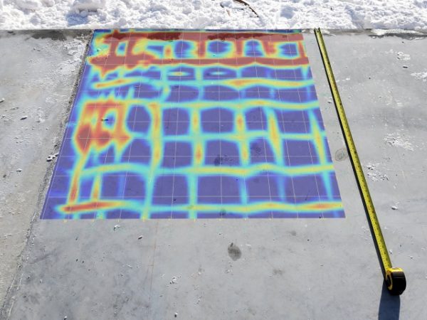
Can we detect corrosion using GPR?
The quality of the signal’s reflection is a good indication of corrosion. Strong reflections/High Amplitude due to the high velocity usually indicate a sound or a problem-free steel reinforcing bars, but weak reflections/low amplitudes by the slowed wave speed indicate a problematic reinforcing steel bar typically due to corrosion. This is because the concrete’s dielectric properties were increased (rust/corrosion has a higher dielectric constant than concrete) due to the effects of corrosion, thus slowing down the wave speed that is weakening the reflection and lowering the amplitude. It will now be easier to identify corroded reinforcing steel bars in a scan. Computer-assisted virtual interpretations of GPR profiles can help create corrosion maps in concrete elements.
When should we use GPR?
The use of GPR is not always the best choice in conducting quality control or surveys. The need to consider many factors before using GPR will help determine the successful application of this method. One of these is the location, logistical issues, and site conditions that can hinder the use of GPR. Second is the project’s goal; the project goal should really be achieved by the GPR’s capacity. Finally, the size, depth, geometry, and orientation of the target should be greatly considered. It is easier to detect a horizontal target than a vertical one. Small targets can be challenging to detect and differentiate from other inconsistencies in the subsurface. In contrast, deep targets could be well beyond the depth capacity of the GPR.
What should be the type of antenna?
The best practice in selecting the appropriate antenna would be to use the antenna frequency to give you the finest resolution. It means that it would depend on what field of application that you are using. It is essential to know that smaller antennas produce shorter wavelength and pulse duration at higher frequencies (800 – 2600 MHz), which means that it provides finer resolution only on shallow depths; larger antennas have a longer wavelength and pulse duration at lower frequencies (12.5 – 200 MHz), which means that it gives coarser-resolution at deeper depths. What does this mean? If you are looking to investigate a 20 cm-thick concrete using a large antenna, then you will struggle with the results since it will not clearly define the changes in the thin asphalt layer due to the coarse resolution. It will be best to use a smaller antenna with a higher frequency especially in concrete scanning.
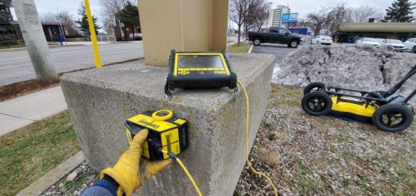
How can we improve data collection?
Many factors could influence the data collection strategy you want to implement, such as time, project site obstructions, required deliverables, and real-time project targets. One way to improve data collection is by collecting data systematically using a grid. This is the best way to create 3D renderings or images for the project. Another thing would be to control the factors that you can, such as selecting the best time to conduct the GPR survey considering weather conditions (wet surfaces could attenuate signal rapidly) and turning off mobile phones that could interfere with the radio frequencies of the GPR.
What are the other Concrete Imaging NDT techniques?
Radiography has been one of the earliest NDT techniques used to obtain a solid shadow image using penetrating radiation. It is commonly used in the medical field. X-ray is a radiography-based NDT technique capable of producing accurate two-dimensional images of the concrete interior with unparalleled high-resolution images. Still, because of their high initial costs, low speed, heavy and expensive equipment, safety precautions, highly skilled personnel requirement and the need to access both sides of the structure, its use has been limited. It also cannot provide depth or thickness estimation.
Acoustic imaging is another type of concrete imaging that includes the use of ultrasonic pulse echo tomography.
Ultrasonic Pulse Echo refers to the use of ultrasound, which is the pitch of a high sound undetected by the human ear. Ultrasonic Pulse Echo is conducted by transmitting ultrasound waves to the surface, which are recorded and interpreted to reconstruct an image using tomographic imaging algorithms. It can determine the position, height and size of a defect. Also, it is not affected by the presence of reinforcements and moisture but is highly sensitive to the maximum aggregate size and is time-consuming to perform in large areas due to the surface coupling requirement. There have been applications where Ultrasonic Pulse Echo has been used alongside GPR to address its limitations in the concrete’s quality control. (Read More About Ultrasonic Pulse Echo Tomography)



Eve Mitchell
I had no idea that a horizontal object was easier to find than a vertical one. I think GPR is such cool technology and I would love to learn more about it. It'd be interesting to find a local company that uses it in daily practice.
John Carston
It helped when you mentioned that it is hard to know changes in concrete detail or small delineations. My uncle mentioned to me last night his friend is looking for a reliable utility locating service for his upcoming project and asked if I have any idea what is the best option to do. Thanks to this informative article and I'll be sure to tell him that it will be much better if they consult a trusted utility locating service company as they can answer all his inquiries.