Low strain pile integrity test is a common nondestructive test (NDT) procedure for quality control and quality assurance (QC/QA) in deep foundation construction. The test can be used to identify physical defects (voids or discontinuity, referred to as pile integrity) in piles, or determine unknown length of existing deep foundations.
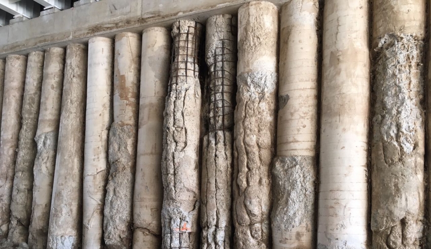
Low Strain Pile Integrity Test belongs to the family of shaft head impact tests, where the response of an impact made on the head of pile head is recorded by a motion transducer (i.e. accelerometer), and used for analysis. Alternatively, engineers can use other tests such as crosshole or down-hole tests for the purpose of integrity test.
Pile Integrity Test Principle
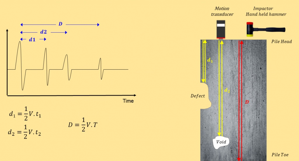
The general principle behind the pile integrity test is relatively simple. By Assuming that the stress wave travels at the speed of C inside the pile shaft, the pile depth can be determined by measuring the time lapse, T, between striking pile head and receiving reflections on pile head.
How To Perform Low Strain Pile Integrity Test?
Pile Integrity Test (PIT) is normally performed by striking the pile head with a light hand-held hammer and recording the response of the pile using a motion transducer (i.e. accelerometer) coupled to the pile head. The hammer strike (blows) generate compressive stress wave that will travel through the pile. This wave is partly reflected from the pile toe or other anomalies within the pile in its way back to pile head. Any change in impedance (due to change in pile cross section, concrete density, or shaft-soil properties) within the pile can impact the reflecting signal.
1- When To Perform Pile Integrity Test?
The integrity testing should be performed no sooner than 7 days after casting or after concrete strength achieves at least 3/4 of its design strength, whichever occurs earlier.
2- How to Prepare The Surface?
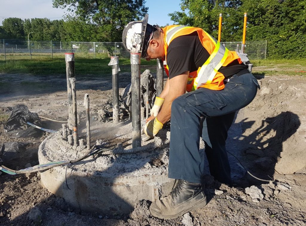
The surface of the pile head should be prepared ahead of the test. The pile surface should be accessible, and above water. All loose concrete, soil or other foreign materials resulting from construction should be removed from pile surface. If there is any type of contamination on the surface, it should be removed (using a grinder) to reach to solid and sound concrete surface.
3- How To Couple Transducer and Pile Head?
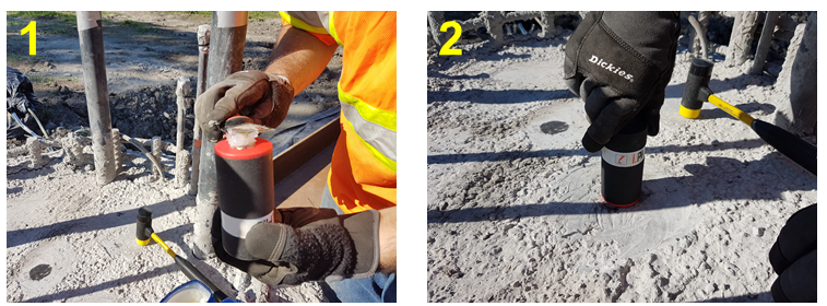
A firm connection between the sensor’s tip and concrete surface (pile tip) is needed for successful application of the test method. A thin layer of Vaselin, or putty is normally used to make a firm connection between the sensor and the pile head.
4- What type of hammer should you use?
Low strain impact integrity testing is performed using a hand held hammer. The hammer can be as light as couple of hundred grams, to relatively heavier options. The impacts induced by smaller hammer have higher frequency content, and shorter rise time. Larger hammers on the other hand, induce higher energy. Sharp and narrow input pulses are reported to be better than wider ones. However, when the size is reduced, the frequencies contained in the impact increases; these waves attenuate faster, and are tend to decrease the ability of investigating longer piles. Hammers less than 1 Kg with a plastic impact tip are ideal for most cases. When pile diameter is larger than 1 m (1000 mm), heavier hammers will be more suitable. The hammer tip should be made of material that does not damage concrete during the impact, as this will impact the test results.
5- Striking Pile Head: Where, How, How Many?
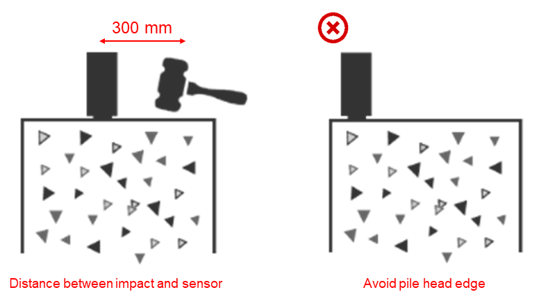
The low strain impact should be applied to the pile head within a distance of 300 mm from the sensor. It is also important to place the transducer far from the pile edge to reduce the effect of edge. Make sure that the impact is applied axially. For inclined piles, make sure the transducer is place perpendicular to the pile surface (parallel to pile longitudinal axis), and the strike direction is parallel to this direction.
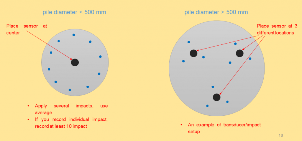
For circular (diameter less than 500 mm) and rectangular cross sections, place the sensor near the center of the pile and strike several times around the pile head (i.e. 10 impacts). Increasing the number of impacts will reduce the effect of background noise, and helps enhance repeatable parts, which will make interpretation easier. For piles with larger diameter (i.e. Diameter > 500 mm) additional locations should be considered to obtain useful integrity information about the pile.
How to interpret Pile Integrity Test Results
The motion transducer collects reflection on the pile head. The measurements can be either acceleration (accelerometer), or velocity (geophone). A typical reflection from a sound pile is displayed in the following graph.
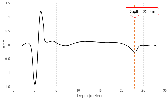
Results can be displayed in time domain (where horizontal axis shows the arrival time of echoes on pile head). Alternatively, time stamps can be converted to depth values. Results can be presented in negative or positive formats. The first peak is usually from the surface wave triggering the motion transducer. In a sound pile, the next major peak is usually the one associated with pile toe. A minimum sampling rate of 25 kHz, and time array length of 100 ms is generally good for evaluating most piles. In the event of using an accelerometer, integration of test results are used to show the measurements in velocity format.
1. Wave Speed Adjustment
The speed of stress wave can be adjusted based on the type and condition of pile material. A number of researchers and engineers have developed correlation tables between the quality of material, and the compression wave speed in the material. For example, wave speed in sound concrete is approximately 4,000 m/s (~13,000 ft/s).
2. Low Pass Filter
Low pass filter is used to reduce the effect of high frequency reflections caused by shear wave influence at the top of the pile and steel reinforcement inside the pile.
3. Amplification
The reflecting signal can get attenuated for several reasons. High impedance, and longer pile length can attenuate the returning signal, making it difficult to identify pile toe. In this case, an exponential amplification function is used across the pile length to amplify the low energy reflections from the pile toe and other internal anomalies. This function is applied if the reflection of the pile toe is not apparent. This function increases the amplitude of signal exponentially with time along the recorded signal. Application of this function should be handled with care, as it also amplifies background noise.
Pile Integrity Test Standards
The test has been adapted by many standards and codes around the globe. The most commonly used standard that is used for performing pile integrity test and reporting is the ASTM D5882-16, Standard Test Method for Low Strain Impact Integrity Testing of Deep Foundations, ASTM International, West Conshohocken, PA, 2016, www.astm.org




Ankush singh
I like how you explain the important info of piling and construction. We need to to improve our technology towards ground improvement techniques. As earth quakes are increasing decade by decade and no matter how solid your upper part of building are, foundation needs to be strong to support its weight. We are also working day and night to provide best Ground improvement services to our customer in India.
Braden Bills
I want to make sure that my new home is sturdy. It makes sense that having it piled would be important! I'll be sure to get a professional to do that for me. They would know the proper ways to prepare the landscape for that.
Non-destructive Testing of Concrete Foundations | FPrimeC Solutions
[…] Low strain pile integrity test […]
What is Pile Integrity Test ? | FPrimeC Solutions
[…] Pingback: How To Perform Low Strain Pile Integrity Test? | FPrimeC Solutions […]
Mohamad Noorfizan
Is there any limitation for PIT? Perhaps in terms of L/D ratio?
janamjeet Singh
How the first arrival of the wave was captured in pile integrity test
Muzzammil
"The first peak is usually from the surface wave triggering the motion transducer. In a sound pile, the next major peak is usually the one associated with pile toe."