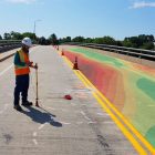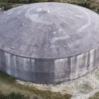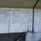

Terrestrial LiDAR scanning and drone inspection helped FPrimeC document an existing concrete water tank for engineering review and geometric analysis.
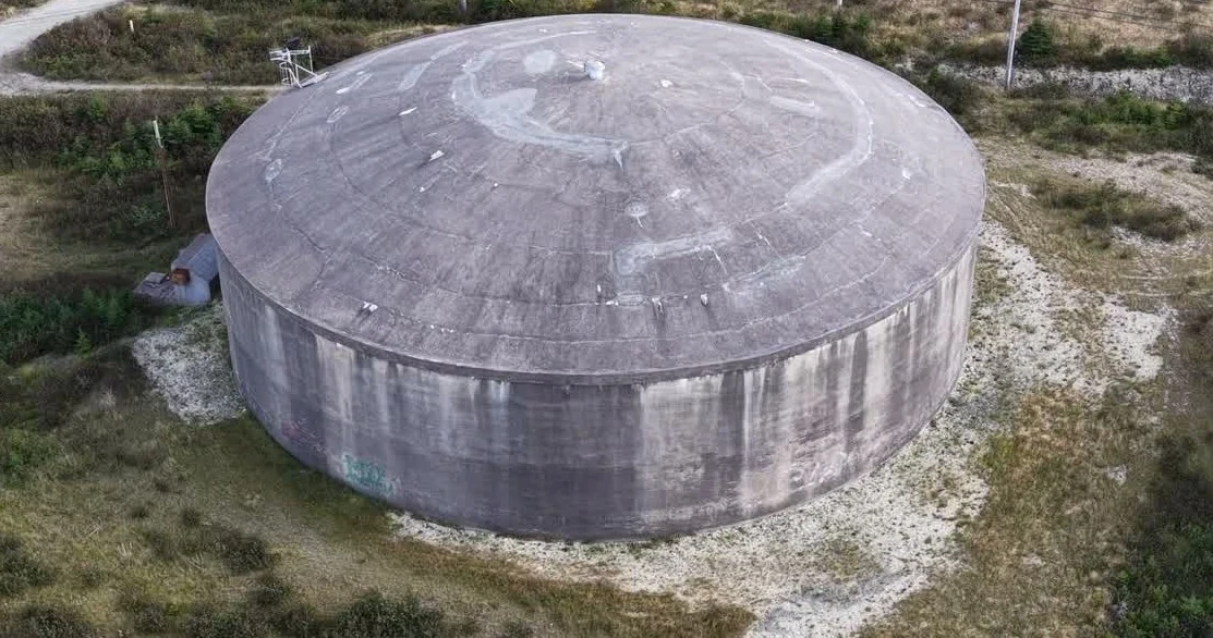
What do you do when the available drawings do not contain the structural details needed to understand an existing water tank?
That was one of the challenges behind FPrimeC’s investigation of an existing concrete water reservoir. To support the structural condition assessment, the team needed a clearer record of the wall and dome geometry, visible surface conditions and locations requiring closer examination. Drone inspection, terrestrial LiDAR and selected testing contributed different parts of that record.
FPrimeC used 3D laser scanning to capture the tank’s interior and exterior with a Leica BLK360. The resulting 3D point cloud recorded the surfaces visible from the scan positions. This reality capture dataset could be reviewed in the office, used to prepare sections and compared with photographs and other inspection information.
Start with the missing information
The available records did not resolve all of the tank’s structural details. One question was how the wall and dome geometry varied across the structure. A few isolated measurements would describe only the locations where they were taken; the team also needed a broader spatial record.
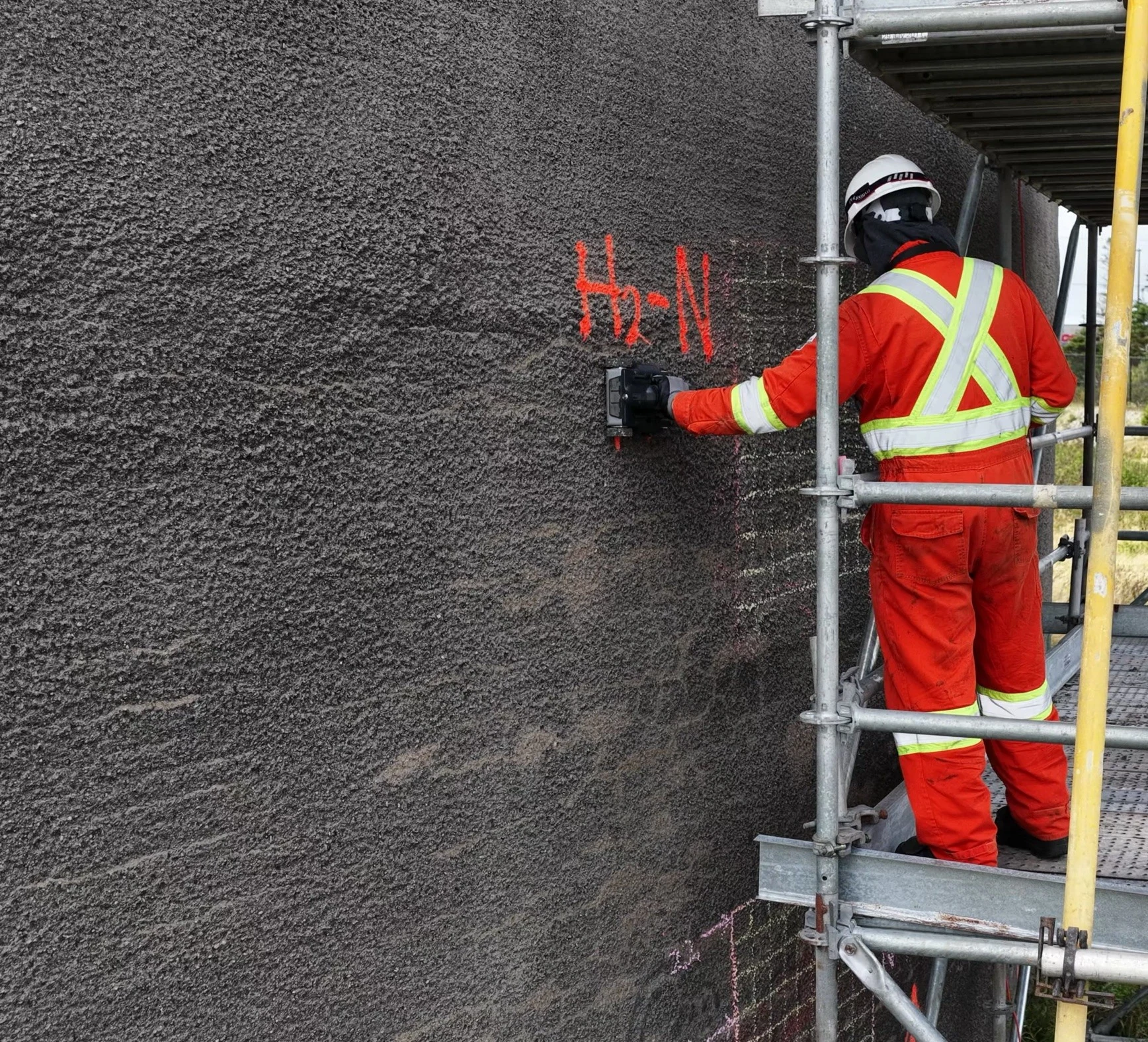
Drilling required careful consideration of the tank’s prestressing. The wider concrete condition assessment combined LiDAR capture with nondestructive testing (NDT), including ground penetrating radar (GPR) and ultrasonic pulse-echo (UPE). The scan record documented accessible surface geometry; the testing contributed separate evidence to the investigation. A surface model alone could not establish the concrete’s internal condition.
The capture objective was therefore specific: assemble usable views of the inside and outside, retain the relationship between those surfaces, and identify where the record could support further examination.
Water tank drone inspection: focusing the fieldwork
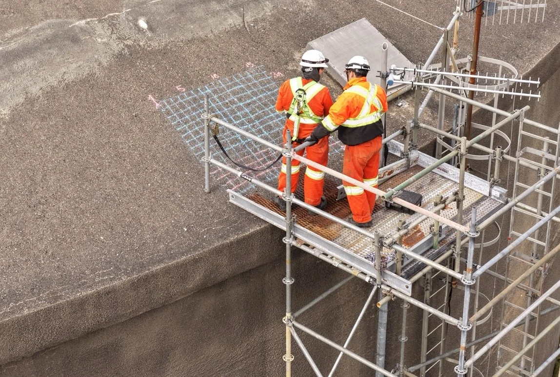
Drone inspection supported the early photographic condition survey of the tank’s elevated surfaces. Before setting up scaffolding for hands-on testing, the team used wider aerial photographs and zoomed views to examine the ring-beam edge. This remote visual inspection helped identify areas of interest and select test locations more quickly and efficiently.
The wider view established the location and surrounding condition. Closer photographs revealed local concrete loss and exposed reinforcement, giving the team specific areas to investigate when planning access and testing. This initial visual review could be completed without scaffold access to those locations.
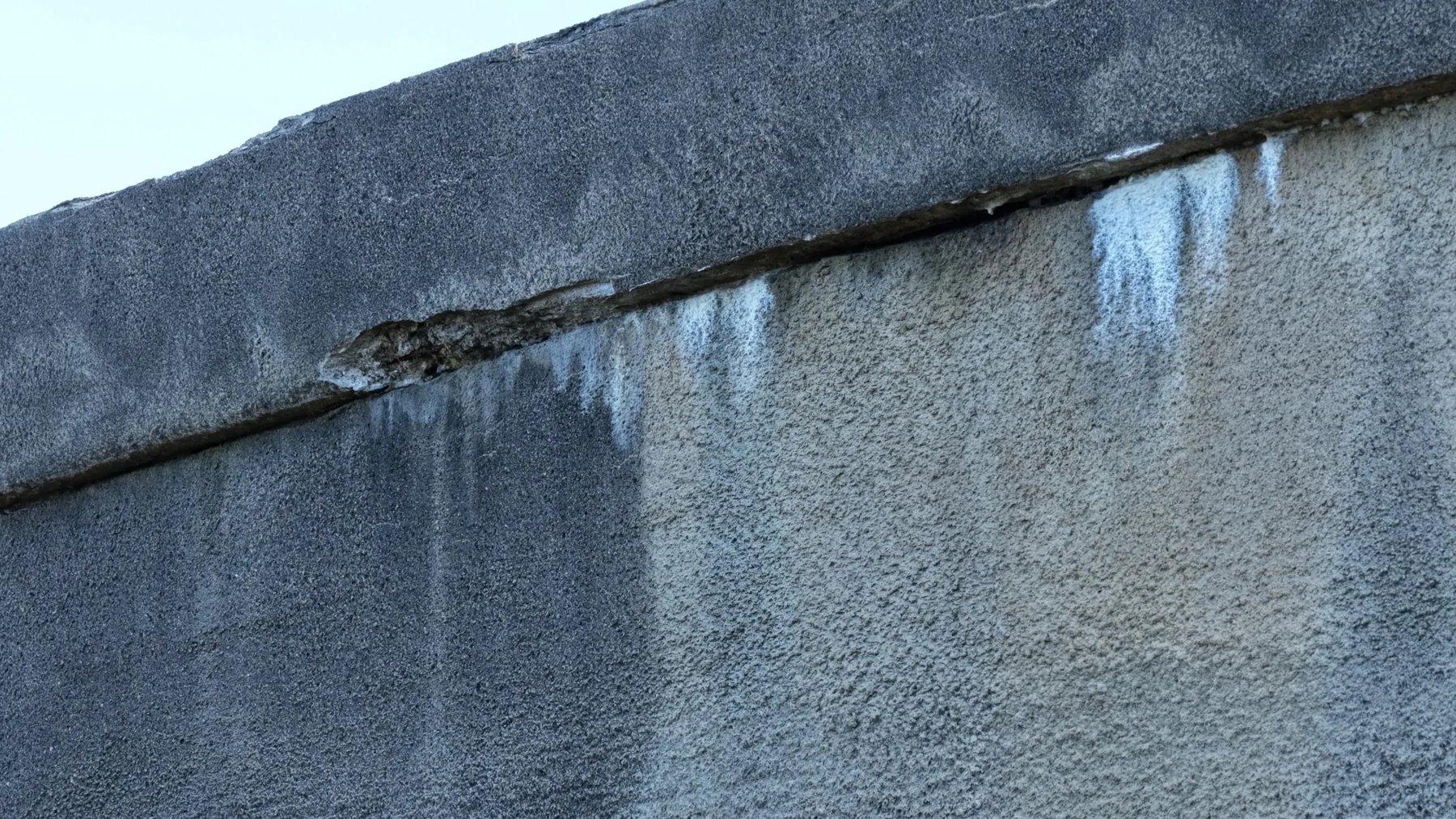
The pre-inspection helped focus the subsequent fieldwork. Close-access testing then followed at selected locations. The photographs document visible surface conditions; the wider investigation used testing and engineering review to assess their significance.
Water tank LiDAR scanning: capturing the structure from both sides
Terrestrial LiDAR captured the concrete structure from multiple positions inside and outside the tank. Each scan added a view of the accessible surfaces. For this point cloud inspection, both sides mattered: reviewing only the exterior would leave the relationship to the interior surface unresolved.
Coverage mattered as much as the overall appearance of the model. An obstruction, an inaccessible position or a surface beyond the scanner’s view could leave a gap. A detailed-looking view of the outside did not establish that the corresponding inside surface was equally well documented.
For an investigation that compares the two sides of a wall or dome, those gaps need to remain visible in the analysis. The useful record includes both the captured geometry and an understanding of where information is missing.
Aligning the LiDAR scans into one 3D record
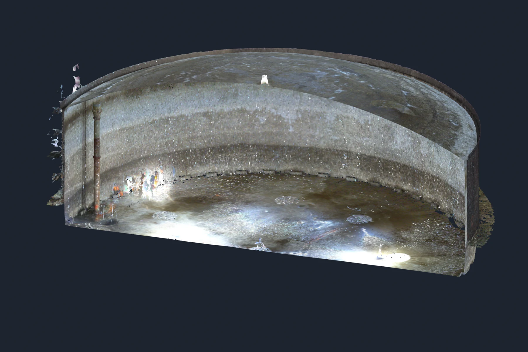
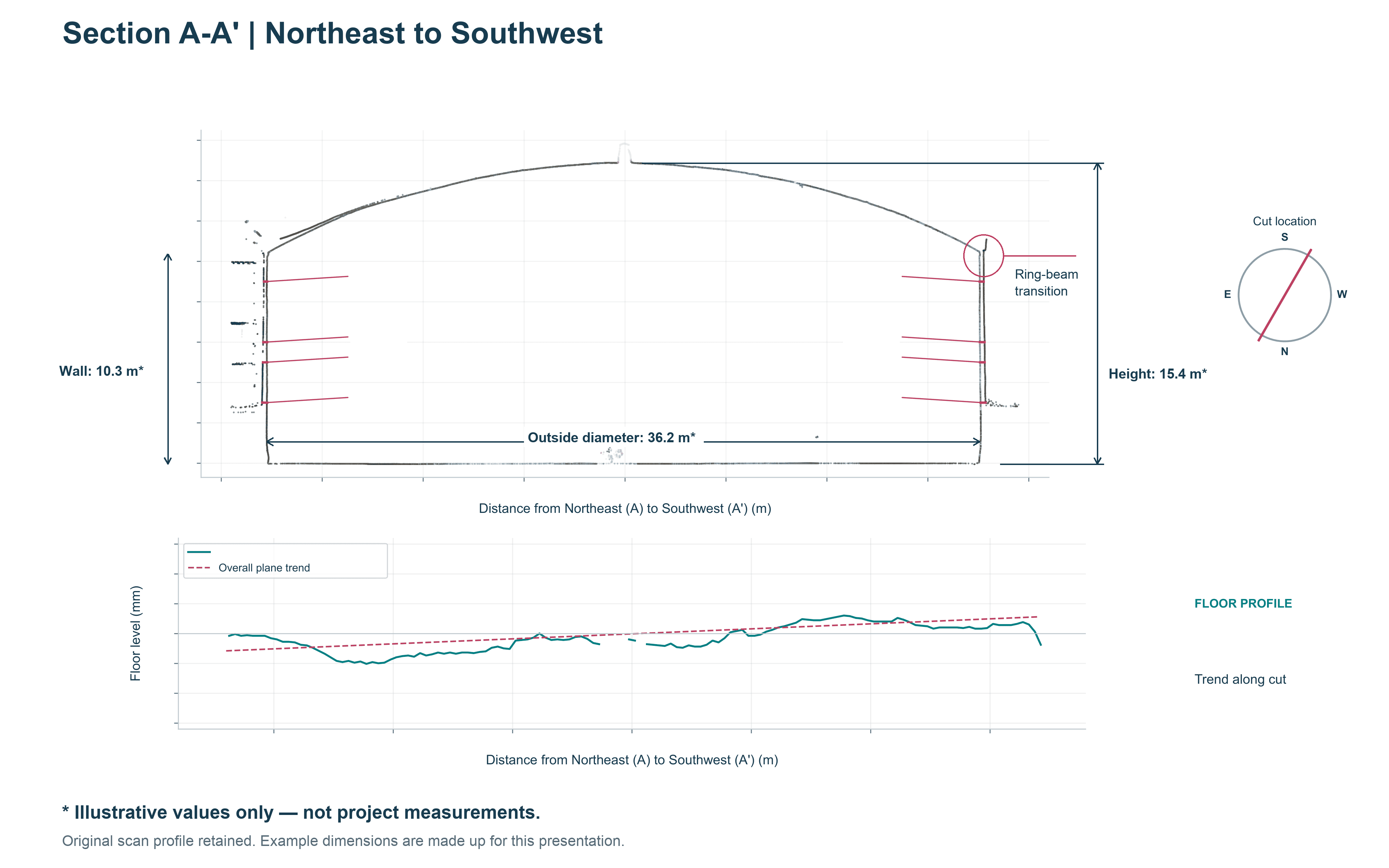
After field capture, the team aligned the interior and exterior scans into a common 3D record. This office-processing step made it possible to review the structure as a whole, extract sections and compare corresponding surfaces. The cutaway below shows the resulting geometry.
Where the scans captured both faces, the team could compare the inner and outer surfaces. Gaps in coverage and uncertainty in alignment limited those comparisons.
Water tank cross-section
A vertical cut through the aligned scans shows the tank’s dome, wall and floor together. The original profile below includes a cut-location sketch and the floor trend along that cut. Three example dimensions illustrate how the overall diameter, floor-to-dome height and straight-wall height can be presented.
A closer look at the ring-beam transition
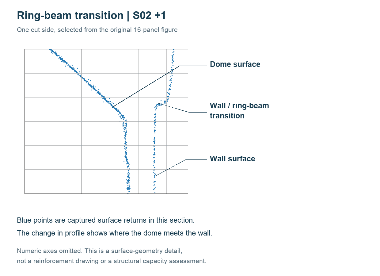
This is the top-right detail from the original 16-panel figure: S02 +1, the positive end of section S02. Each panel represents one side of a cut; the eight original cuts produced two end views each.
The blue scan points show the local surface profile where the dome meets the wall at the ring-beam transition. Isolating one view makes that change in shape easier to follow. It documents visible surface geometry; it does not reveal reinforcement or establish structural capacity.
What the 3D record adds to the investigation
For a digital concrete condition survey, the useful output is a record that connects the inspection question to evidence the team can revisit. In this project, photographs document visible conditions, the point cloud retains captured geometry, and the cross-section shows the relationship between the dome, wall and floor. The wider drone photograph shows where the team observed local concrete loss along the ring-beam edge.
This combination supports digital inspection of concrete structures by giving the project team photographic context and a spatial record to examine alongside NDT information. It helps distinguish what was observed, where a geometric comparison was made and which areas remain uncertain. Interpretation belongs within the broader structural condition assessment, alongside available records, testing and engineering review.
The aligned scans gave the team a record of the tank it could revisit alongside the photographs and field observations.
Planning an investigation?
Start with the information your team needs.
Planning a concrete condition survey using drone inspection or 3D laser scanning? Share the asset type, available drawings, access constraints and the engineering questions the investigation needs to answer. FPrimeC can discuss the scope of photographic documentation, LiDAR capture and selected nondestructive testing, together with the records needed for review.