Concrete Imaging and Scanning are used to assess the location and extent of sub-surface defects. Different non-destructive test methods have been developed and used over the past few decades. The following article briefly describes some of these methods, and their application in the structure inspection and structural condition assessment.
What is Concrete Imaging and Scanning?
Concrete Imaging and Scanning is generally referred to a group of non-destructive tests (NDT) that can locate, and quantify sub-surface anomalies and defects (targets). Several Imaging and Scanning technologies have been developed over the past few decades:
- Ground Penetrating Radar (based on Electromagnetic Field),
- Ultrasonic Tomography (based on the propagation of ultrasonic wave),
- Electrical Resistivity, and Half-Cell Corrosion Mapping (based Electrical and Electrochemical properties), and X-Ray
Moreover, the underlying physics of ultrasonic and electromagnetic wave propagation in solids have been developed to address certain challenges in special structures, such as mass concrete dams, and foundations.
Why Do We Need Concrete Scanning?
Concrete scanning might become necessary in different situations:
- structure inspection and condition survey of existing buildings,
- locate steel rebar in slabs and walls,
- locate defects such as voids and discontinuities in concrete slab on grades
- locate live conduits ahead of coring and drilling
- Corrosion inspection and monitoring
NDT Methods for Concrete Imaging and Scanning
Different non-destructive testing methods have been developed for concrete imaging and scanning. In this article, we will review some of the most famous NDT methods for concrete imaging and scanning.

Ground Penetrating Radar for Locating steel rebar and live conduits, and major voids in concrete slab-on-grade
1. Ground Penetrating Radar – GPR
Ground penetrating radar (GPR) is a widely used non-destructive method for scanning concrete. GPR uses pulsed electromagnetic radiation to scan concrete. GPR consists of a transmitter antenna and a receiver antenna, and a signal processing unit. GPR emits electromagnetic pulses (radar pulses) with specific central frequency to scan the subsurface medium. The reflected waves from subsurface layers, and objects are captured by the receiver antenna.
Applications and Use
Ground Penetrating Radar provides a cost-effective approach for scanning large areas. GPR scans can be performed at traffic speed (ideal for large areas, such as bridge deck scanning).
- Locate steel reinforcement in concrete elements
- determine rebar location and spacing
- estimate concrete cover thickness
- Locate live conduits and pipes
- Identify major voids and discontinuities in concrete slabs
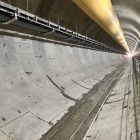
- Inspection of tunnel lining
Limitations of Use
- GPR scans do not provide information on the mechanical properties of concrete (i.e. concrete strength)
- GPR scans do not provide information on the corrosion condition of steel bars

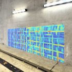
Ultrasonic Tomography (MIRA) scanning of a concrete bridge deck to determine thickness, and locating delamination
2. Ultrasonic Tomography – Pulse Echo
Ultrasonic Tomography can be used for scanning sub-surface voids and defects in concrete. Tomography uses ultrasonic shear waves to study multilayer properties of concrete.
The concept behind this method relies on the propagation of stress waves through materials. A transmitter introduces a stress pulse into the object at an accessible surface. The pulse propagates into the test object and is reflected at the interface of internal targets (air voids, steel bars, boundaries). The emitted impulse and the reflected acoustic waves are monitored at the receiving transducer. Mathematical solvers are used to reconstruct the location and extent of internal anomalies.
Applications and Use
Tomography and Ultrasonic Pulse Echo (UPE) provide an effective method in evaluating concrete defects:
- Estimate the thickness of concrete elements (thin elements through mid-range thickness)
- Detect internal voids and flaws.
- Detect shallow depth cracking and delamination
Limitations of Use
- Concrete scanning using tomography or UPE requires small spacing, making it time-consuming for scanning large areas.
- Testing on rough concrete surface might be challenging (sensor-concrete coupling)

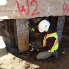
Concrete X-Ray might be a viable option in heavily reinforced thin concrete members
3. X-Ray Scanning of Concrete
X-Ray imagining in concrete is very similar to X-Rays that is used in imaging laboratories. Concrete scanning and imaging using X-ray can be done using conventional methods, or the digital medium. The major difference is how they process the image. The X-Ray scan can be used to locate steel bars in heavily reinforced elements.
Limitations of Use
- Since this technology is using high energy X-Rays, usually a clearance is needed before conducting the test. This means that a clear distance of approximately 15m to 25 m should be observed for the purpose of testing. Most of X-Ray imaging projects are scheduled for night shifts, or after-hours, to reduce the cost and efforts needed for preparing safe clearance, and conducting test.
- X-Ray attenuates as it travels through concrete; therefore, it is strongly recommended to limit the scan depth to appx 200 mm or thinner elements.
- The test results should be processed and interpreted by an experienced technician to map the images on the concrete slab.
- Another limitation of the method is that it does not provide information about the depth of sub-surface targets.

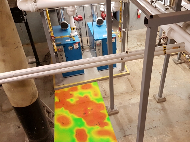
Half-Cell Corrosion Potential Mapping – Identify locations with higher likelihood of corrosion
4. Half-Cell Corrosion Potential Mapping
Half Cell corrosion mapping is an effective method for assessing the likelihood of corrosion activity in concrete structures. Half-Cell test works based on measuring the potential difference (electrochemical) of an arbitrary point on the concrete surface and a standard portable half-cell, typically a Cu/CuSO4 (CSE) standard reference electrode. The test is usually performed on a systematic grid, and measurements are often displayed as spatial distribution (2D contour maps) of potential value.
Applications and Use
- Evaluating the likelihood of corrosion in concrete elements;
- Evaluate the effectiveness of concrete repair
Limitations of Use
- The test cannot be performed over asphalt toppings;
- The test is sensitive to concrete humidity, and temperature
- The test cannot be performed on elements with epoxy-coated rebar

Seismic Tomography for scanning mass concrete elements
5. Seismic Tomography for Mass Concrete
Seismic tomography is a special test setup based on the very concept of Ultrasonic Pulse Velocity. In this method, an array of multiple receiving transducers are placed and fixed in the test locations, while the sending transducer is moved along a systematic grid. The pulse generated by transmitter are received by receiving transducers. The pulse velocity at each trajectory is measured. The results are demonstrated in a 2D or 3D seismic tomography contour maps that shows the condition of concrete element. Seismic tomography is ideal for testing the large scale concrete elements.
Applications and Use
- Detect major voids and internal defects in mass concrete elements (i.e. dams, mass foundation blocks, etc)
- Identify weak locations (correlating-indirect- wave velocity to concrete strength)
About Author
Dr. Hamed Layssi, PEng is the CEO and structural engineer at FPrimeC Solutions. He has been involved with the Concrete industry for over 15 years as a professional engineer, industrial research and development specialist, researcher and scholar. Dr. Layssi is a registered professional engineer in Ontario since 2014, hold a PhD from McGill University, Canada, and have received the 2018 entrepreneurship award from the PEO, Ottawa Chapter.
Follow Hamed on LinkedIn for Daily updates on applications of NDT method in structural evaluation

Advanced Concrete Scanning and Imaging Solutions
Discover our innovative imaging solutions for a wide range of engineering applications.
Request Information
Concrete Scanning
What is Ground Penetrating Radar | FPrimeC Solutions
[…] of ground penetrating radar and its broad range of applications, make it distinct from existing NDT methods. GPR can detect subsurface events and objects using the electromagnetic radar impulse, ranging from […]
Angela Waterford
My professor told me that I should do a presentation regarding non-destructive testing, so I'm doing my research on what the usual applications are for concrete buildings. Thanks for elaborating that ultrasonic tomography is usually used for detecting flaws in a structure. I think I'll consider asking an expert more about this so I can present my research next month.
FPrimeC
Dear Angela,
Please feel free to reach out to one of our experts, Dr. Hamed Layssi or Dr. Farid Moradi (co-founders at FPrimeC). They are both experts in concrete structures, testing, and NDT. All the best. FPrimeC
Musa
Am currently researching on the use of thermal infrared camera as a NDT method of bridge integrity test, with the light you have xray on the thermography its quiet appreciated and also a pointer to what it seems i want to do. Thanks
Engr Musa
FPrimeC
Hi Musa.
Please find the following research by TRB and FHAW : http://onlinepubs.trb.org/onlinepubs/shrp2/SHRP2_S2-R06A-RR-1.pdf
There are sections that are relevant to your questions.
Regards,
Rajendra Prasad prasad Sharma
If you have any PPT on NDT, I need it make familiar the field staff. If possible please mail it to me.
Thanks and Regads
PCTE
Methods shared for concrete imaging, and scanning are informative. People who are looking for such information would find it useful. Thanks for sharing this with us!
Olivier Simon-Boursier
Hi,
I'm working in a society that managed important infrastructures in my city as an intern in research and development. During the construction of one of our bridges, about 90 years ago, a time capsule was introduced in one of the piles. We lost track of it and we are now looking to find a method to detect steel object in massive concrete/stone structure. We already tried a ground penetrating radar without any result. The box is in lead (about 46 cm3).
Do you have more information on the other method?
Taylor Hicken
I appreciated it when you shared that GPR is a widely used non-destructive method for scanning concrete that uses pulsed electromagnetic radiation. It emits pulses at a specific central frequency to scan the subsurface medium. I would like to think if a company needs to hire a GPR service, it should consider hiring the one that is reliable and experienced.
Chance Cook
It's good to know that there are non-destructive methods for scanning concrete and that ground penetrating radar is one of them. I head it can be quite useful. Glad to see how it works from another source.
Beverly Minyard
Thank you for including a section on what concrete scanning is used for. My brother-in-law is a contractor and him and my dad were talking about concrete scanning the other day and I was super lost. Now I know that it can be used for a ton of different things including locating steel rebar in concrete!
Kouros Momeni
What is a practical method of finding embedded objects in concrete that is more accurate/(provides for less misses) than GPR?